Deflection
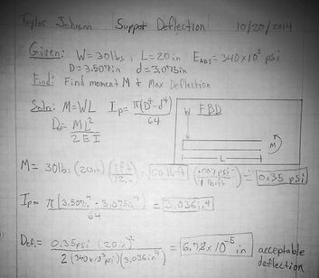
To optimize the weight, size and cost of the bike rack, deflection at the load was analyzed. Refer to Figure A-1 for examples of the calculations used for the analysis. To ensure safety for the user and check one component of stability the Deflection formula: Def=ML2/2EI was used to check if the support members would deflect significantly under load. For this formula an makeitfrom.com was used to find the modulus of elasticity E=340x103 psi for ABS plastic. The I value was derived for the size of pipe used. For round pipe I= pi(D4+d4)/64=3.036in4.
It turned out that with a 3” pipe there would only be 6.78x10⁻⁵in of deflection. This is below the required value for deflection so the 3” pipe is rigid enough for this application. Finally the deflection equation was run for the various common diameters of ABS pipe. This showed that even the 1.5in OD pipe satisfies the deflection requirement. The 1.5in pipe only deflects 6.73x10⁻⁴in. To try to maintain a safety factor of 2.0, two inch pipe will be used in the horizontal supports.
The displacement of the vertical pipe under 30 lb loads was found using displacement and slope at the loads. This method accounts for the instantaneous displacement at each load. It also considers the slope of the displacement as the top load is placed above the bottom load and combines them for a comprehensive analysis of the vertical member displacement. The lower load displacement came out to be 0.15 in and the upper load displacement 1.07in. Together there should be about 1.22in of displacement at the top with two 30lb loads. See appendix A4-5 for specific calculations.
.
Statics
The analysis was conducted with the following assumptions: The fittings and joints are treated as continuous pipe, and bikes weight 30lb each. To analyze the statics of the device, the weights of the components were found using 3in pipe at 1lb/ft. Figure A-3 illustrates this process. With the forces acting through the centroids of their given shapes and the orientation of the bike loads the resultant forces were found (Figure A-4). The reaction force at the feet of the rack was found to be N=71.7lb (Figure A-4). With this data the sum of the moments formula was used to find the reactions on the vertical member at A and B to be 16.1lb. The rack will not tip if the force of friction at the feet can overcome the reaction forces off the wall (2 x 16.1lb). The coefficient of friction (µ) for rubber is 0.50 to 0.85 according to the engineers handbook. The calculation for friction force (µN) resulted in a force of 50.2lbf (Figure 5) which is greater than the wall reaction force of 2 x 16.1= 32.2lbf.

Figure A-1: Deflection at the horizontal load bearing memebers.
Figure A-3: Weights and forces.

Figure A-2: Deflection at the vertical member.


Figure A-4: Reaction forces.
Figure A-5: Friction force.